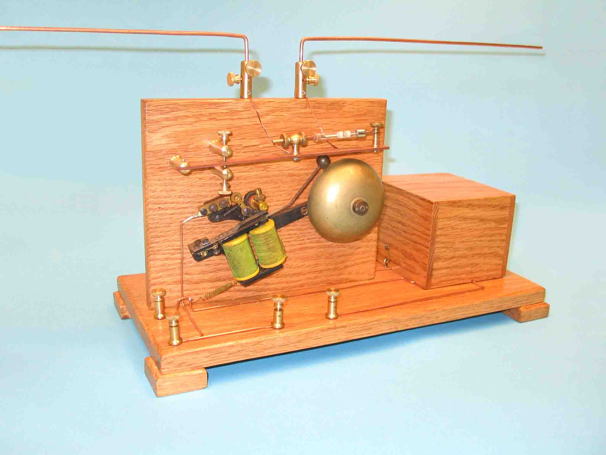
Replica of Hülsmeyer's coherer receiver of ≈ 1904/05
Hülsmeyer's
receiver replica, state of the art of 1904/1905
The two contacts on the left-hand side can be linked onto a remote bell. The two
contacts in the centre, supplies the bell-circuit, which works satisfactory with
9 volts. This somewhat high voltage, is favourable due to its increased tapper
power.
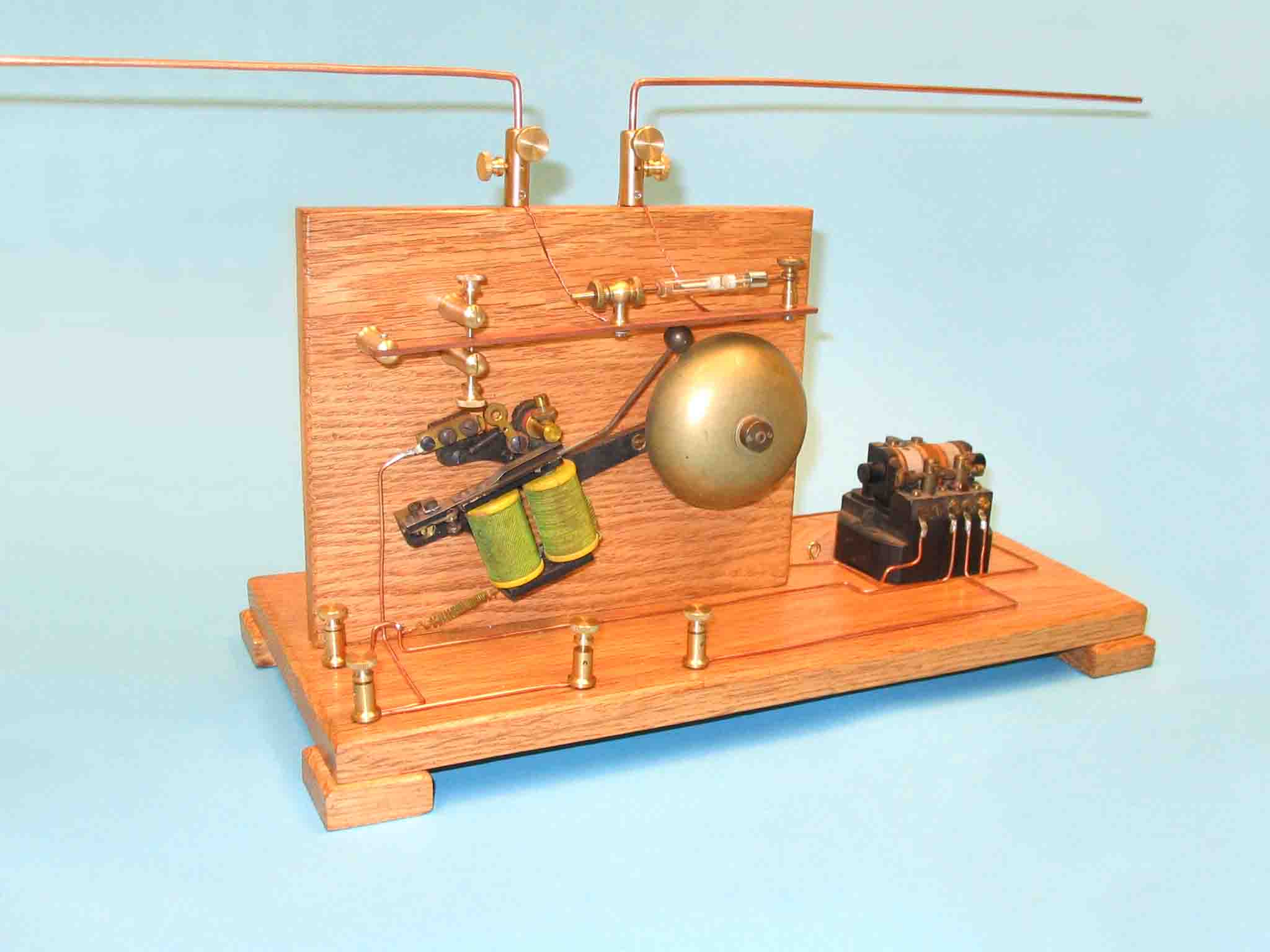
View of the Hülsmeyer receiver replica with relays cover being removed. This relays differs from the type Hülsmeyer employed. This relays-type originate, nevertheless, from the early 1900s.
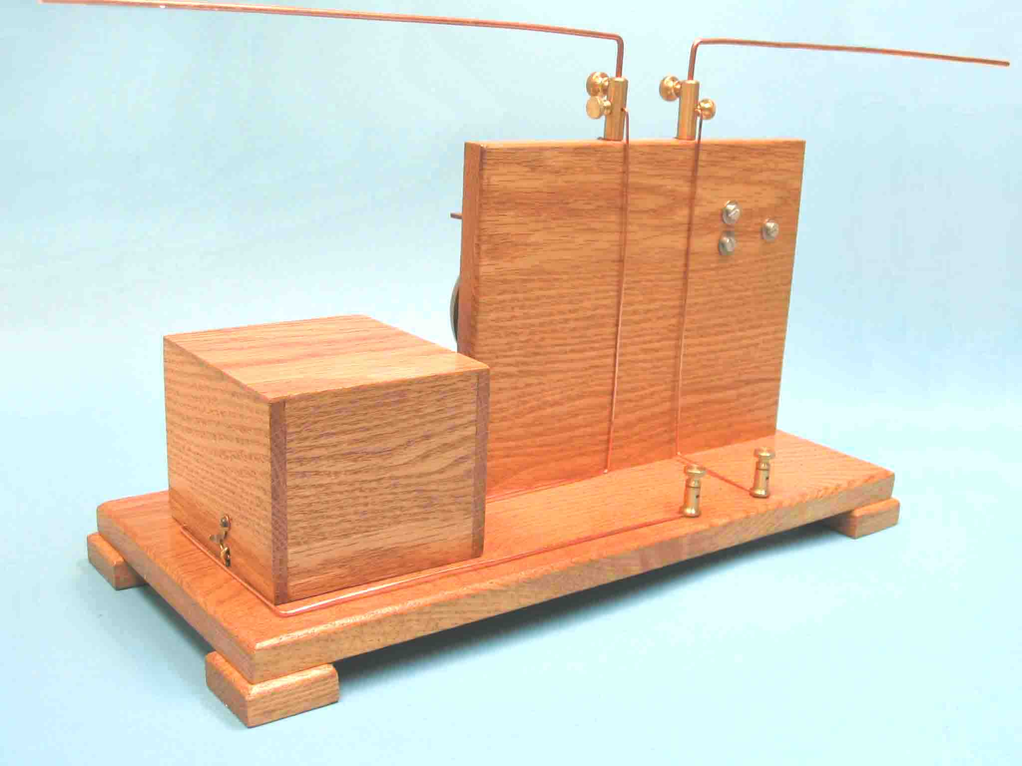
View on the rear side of the Hülsmeyer replica (copy)
The two contacts has to be linked onto a 4.5 volt battery, which supplies the relays-circuit.
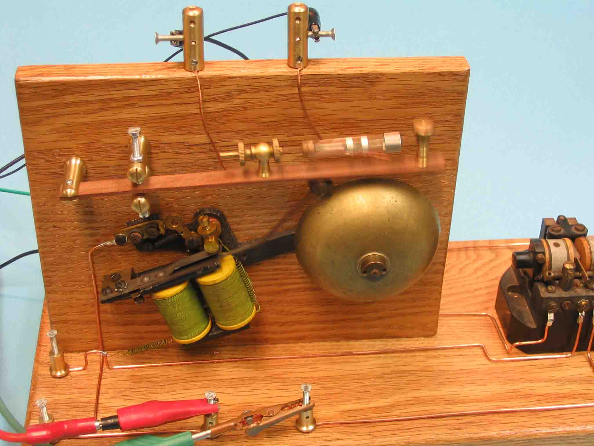
The “out of focus” of the coherer on this photograph, is owing to the actual vibrations of the coherer under test (DUT).
We have
investigated the de-cohering effect of Hülsmeyer’s receiver design.
It appeared, that it is significant to, mutually, adjust all vibrating
components of the system. Such as: the wooden mounting-strip of the coherer -
the resonating tapper-mechanism and the electrical/mechanical parameters of the
coherer. If these do not match, an aperiodic vibration is resulting. It proved,
that correct alignement of the system increases its overall sensitivity.
We have also, briefly, investigated Marconi’s patent application (1896) of: inserting RF chokes in series with the polar-relay circuitry. The receiver sensitivity increased about 20 dB.
This replica (copying)project has been commenced on 16 October 2005.
Back to: Archive displays
Back to: Radar I
![]()