Command transmitter device (unidentified type)
This beautifully, 3 dimensionally, built command-unit represents a magnificent example of space saving technique, deployed by the Germans between 1937 - 1945.
Its supposed purpose is not yet fully clear to us.
What we know
is that:
it has been designed and built between 1942-1945
it must have been manufactured in one of the Dutch Philips works (this does not
necessarily mean that it was a Dutch establishment. It could also have been made
in Belgium, or even in France). Although, we could not find any identification
numbers, the use of typical Philips type resistors and capacitors indicates,
that Philips was, for this occasion, the production contractor.
We know, that Philips was involved, to some extent, in the German wartime electronics production up to the liberation of Eindhoven (third week of September 1944). However, they also possessed production capabilities in Germany as well. But, these were mainly involved in valve (tube) manufacture (Valvo works). Nevertheless, Philips maintained a sales office in Berlin (located at the Kurfürstendamm).
This device consists of a quartz oscillator stage and multiplier stages. Its transmitter frequency can be estimated for > 300 MHz.
Although we do not know its purpose, the existence of a tone selecting (detector?) circuit indicates, that it had a command function.
Considering its compactness, we may assume that it had to be deployed in airborne systems (V2 = A4 or that like). Whether it had to act in a transponder mode cannot be derived from its circuitry, but might well be contemplated.
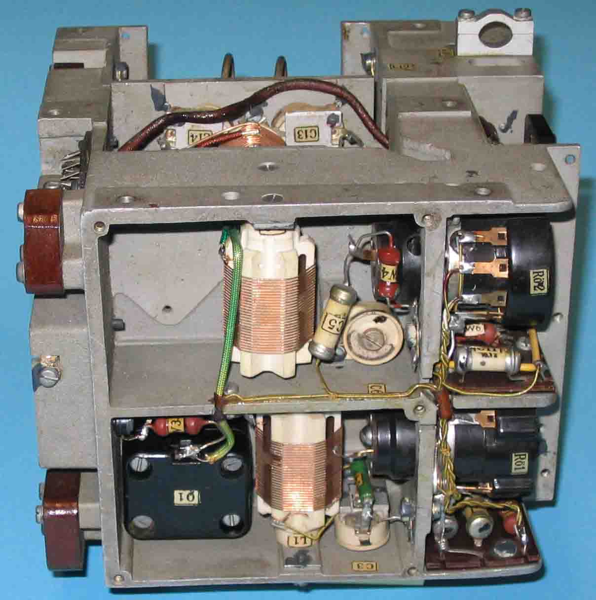
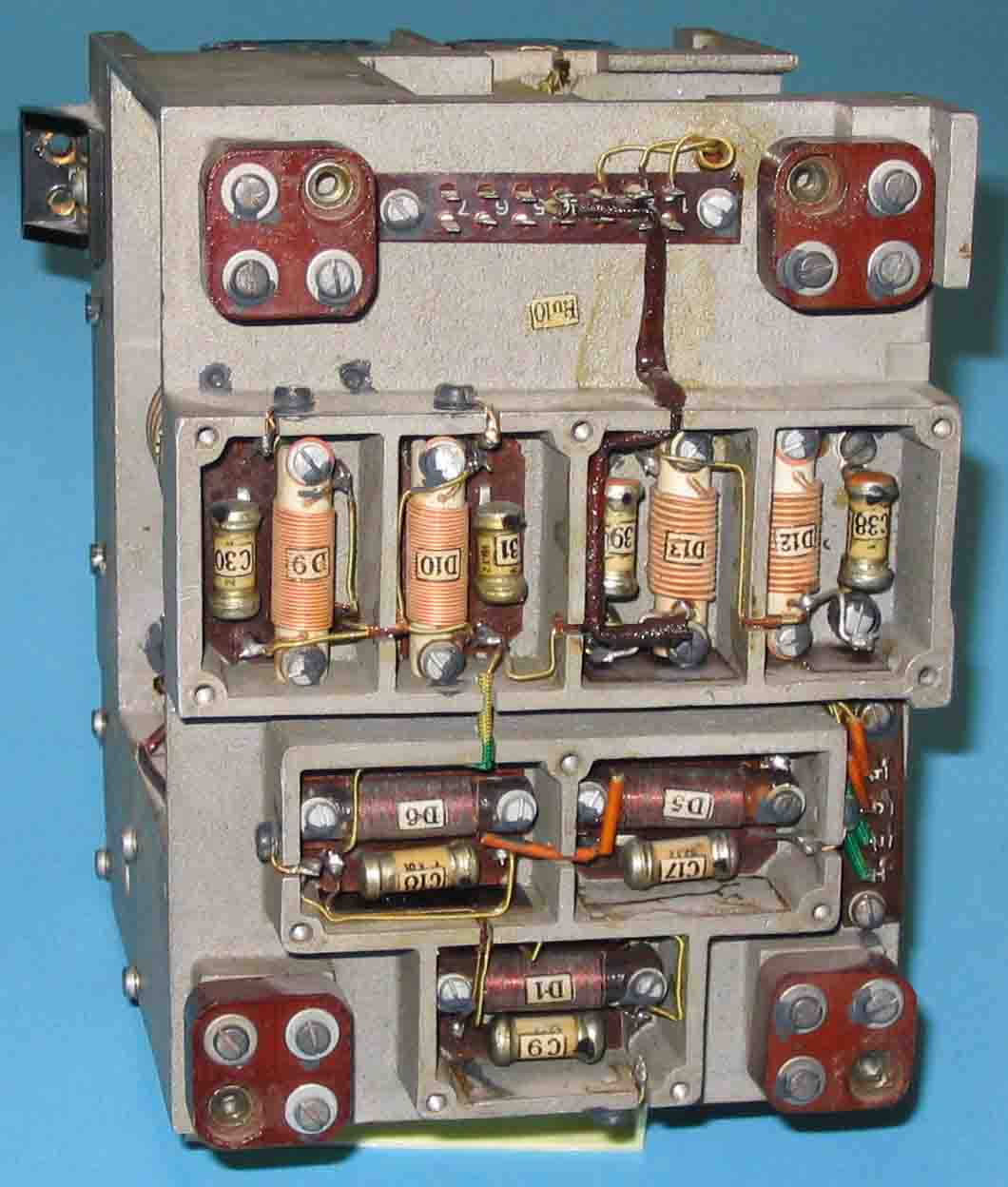
Quartz Q 1, is the frequency determining component. The two coils clearly indicate that they used frequency multiplication. These stages employed RV12P2000s valves (tubes). This was a widely used general purpose valve. “C 5" was of the so-called Sikatrop type(originally designed by Siemens & Halske, "trop" means tropical usage), but probably made by Philips themselves. These components were of very high quality, as they were hermetically sealed off from their environment. Even after > 60 years, they can hold (maintain) their original specifications! Consider also the use of ceramic disc-trimmers, which were originally designed (invented) by the Germans (Hescho) in the mid 1930s.
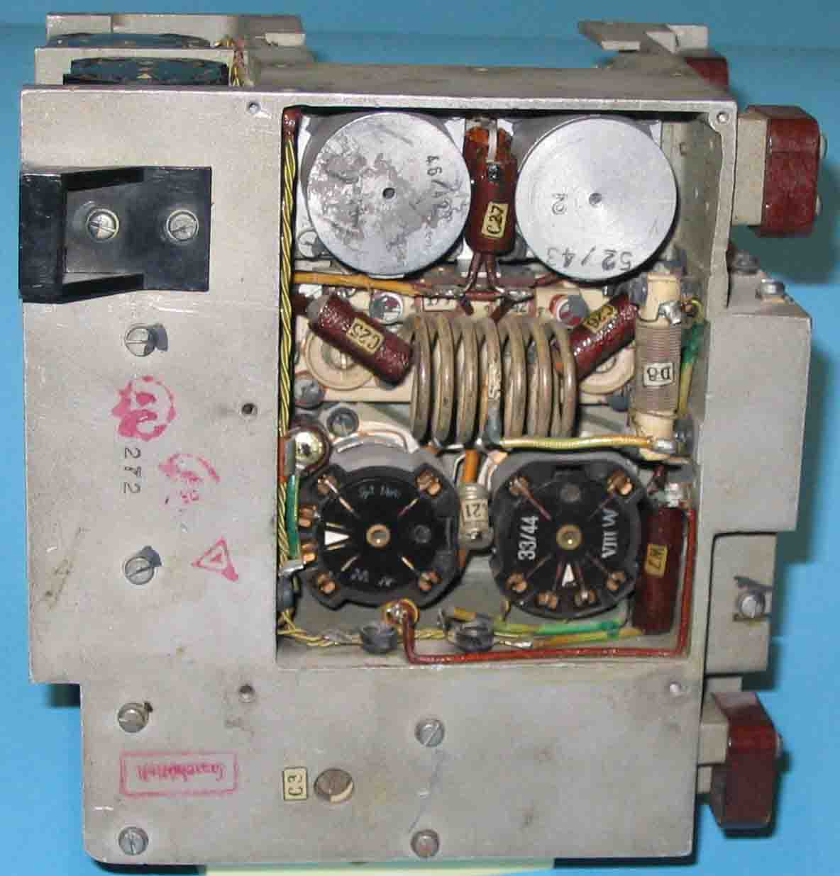
The two lower RV12P2000s (one ear-marked: week 33 of the year 1944), must be the push-pull driver stage at VHF level. The two aluminium discs in the upper part of this photograph, are the cooling and grip section of the VHF/UHF triodes type LD 1. Although, one valve is ear-marked 52/43 (last week of December 1943), this does not necessarily mean that these valves originated from the supposed original date of apparatus acceptance. The red text on the lefthand side of "C3" indicates that this device had gone through a "vibration test procedure".
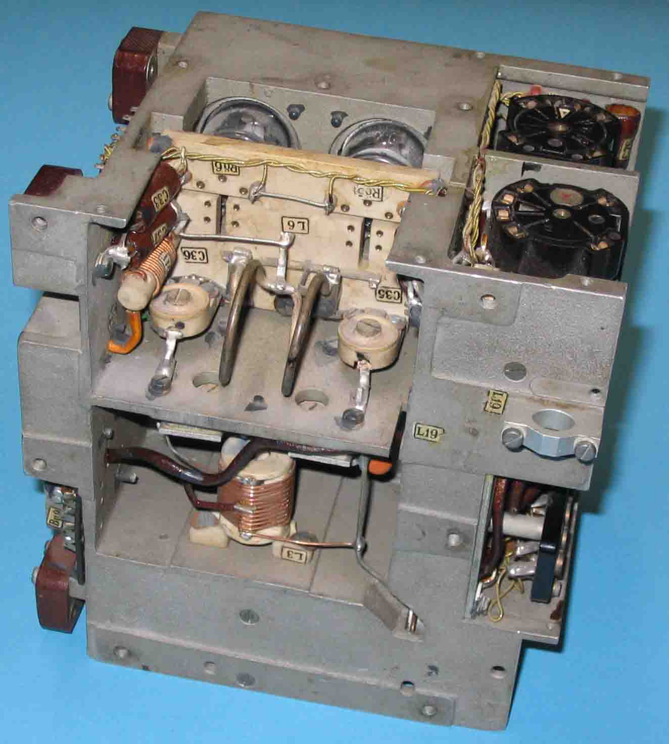
L 6 in
conjunction with valves Rö 5 and 6, represents the UHF transmitter output stage.
L 3 in the lower compartment, is the grid coil of the previous frequency
multiplier stage (2 x RV12P2000) in the former shown photograph.
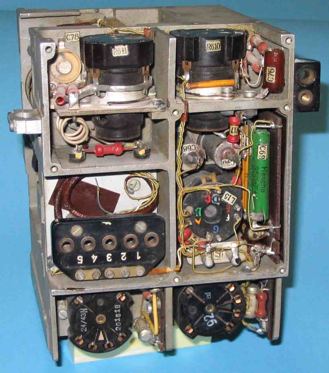
Rö 11 might
be a part of a HF detector stage.
Rö 10 is part of a tone-selector circuitry.
The two lower RV12P2000s are the two first transmitter stages (quartz 1, and its
frequency multiplier).
The components around L 15 and C 60, are part of the low frequency tone-selector
circuit (stage).
The way in which the RF signal is linked onto the input of valve Rö 11 indicates
us, that an adjacent module was most likely to be employed.
The very neat construction, and the proper way of screening off, is a typical example of German filtering technology (philosophy).
It can also be seen, that this module was isolated mounted in the system. Most likely to prevent the system from uncontrollable ground currents (guarding), which was a commonly used German technique (pratice).
If someone can add any kind of information onto this subject, please forward it to:
![]()
Back to: Archive displays
![]()