Köln E 52, how to re-calibrate its first local oscillator professionally?
I have been engaged in restoring the legendary Köln (Koeln) receivers for several decades (started prior to 1970). It proved, however, that in some respect it is very difficult to re-adjust(restore) the frequency reading of the microfilm projection. Although, very comprehensive Köln literature is available now, no one else has solved this problem. (Although, Conrad von Sengbusch and a colleague, published two nice and comprehensive papers on various aspects of “Köln” apparatus).
I have guessed for sometime, how Telefunken may have solved this task in the early 1940s. Consider for Köln receiver generally, my paper on: “Aspects of German Engineering in the 1930s” being my IEEE Bletchley Park conference contribution of June 2004, accessible on my website [1]. Regard also, Telefunken’s secret wartime catalogue of 1941, called: “Luftbodenprogramm”. Which is, most likely, the only remaining copy and is provided on my website too. [2]
Let us follow, for this occasion, the reference notes which I made during the restoration of a Köln E52a1, scale number 1876 on 1 May 1992. Specialists regard the hand-written number painted on the microfilm glass disc as ‘the’ apparatus number. Hans-Ulrich Widdel and colleagues have proved, in an interesting statistical paper, that scale numbers had only been given ones and that this is the only reliable source of product information. [3]
Let us reckon roughly, that there is no means that (early)Köln E52a receivers can be re-adjusted fully. Because, Telefunken sometime did not build-in any means to re-adjust the capacitive off-set of the scale.
This explanation is primarily meant for specialist.
However, briefly explained: it is custom to adjust to two points on a frequency scale. One at the lower end (called L-end and is controlled by adjusting the inductance of the oscillator coil) and one at the upper end of the scale (called C-end, here a trimmer capacitor is coming in force). Early Köln receiver did not had a trimmer, by which means C-end of the scale can be re-adjusted. This must have caused them soon difficulties, and the second(a bit simplified) version, known as E52b..,E52a2..., was provided with accessible (additional) trimmers.
Adjusting the (first) local oscillator (LO) is, by its nature, always a kind of compromise. The super-heterodyne principle is based upon the fact that the signal frequency of a receiver is mixed (either multiplicative or additively) with an off-set signal at a different frequency. In principle it does not matter whether this frequency is below of above the receiver channel (mostly, LO is above the receiver frequency). The sum- or difference, of these two signals, determines the so-called IF-frequency (intermediate frequency). The Germans use the word “ZF” (Zwischenfrequenz). Both signals have to be tuned over a particular frequency band and have to stay in concert.
When a tuning capacitor is being rotated over an angle of say φ, this will result in a frequency shift of say Δf. Now a difficulty is starting to emerge! How can we control two different frequencies, which are being tuned over various frequency bands (ranges) (sometimes even over one octave!), keeping them always in a constant IF difference (notice that all tuning capacitor sections are being ganged and tuned by one tuning knob only)? (Köln employed a six section tuning capacitor) Like in most cases, concessions (compromise) have to be made. Generally resulting in the so-called “two point” technique.
Figure 1. Expressing the so-called “Gleichlauf” deviation of receiver tuning versus the local oscillator, in the frequency domain. Vertically, the LO frequency (deviation) off-set to its nominal value (using a different scale, of course). It may well be, in contrast to this drawing, that the deviation off-set does not cross the frequency (base) line at all (passing sign).
As we can see in this figure, the two points are being designated not at the extreme end of the frequency scale.
What, in particular, made Köln alignment so difficult?
The revolutionary Köln receiver consist of an entirely modular structure. [2] All sections were manufactured at various sites (for instance, the IF module was manufactured by LMT in France, and the power supply was made somewhere in central Europe), being only brought (fit) together when it should finally be assembled. The three switched RF modules had, of course, to be screened-off from environment. Two stages with all the necessary RF tuning coils, and the third one implementing the local oscillator (LO) as well as the mixer coils and capacitors. *
* The local oscillator of Köln receivers is tuned over a quite wide frequency range. Hence, the ratio of L/C is changing considerably too. This will result in higher oscillator (LO)output, when frequency is increasing. The receiver signal versus the LO output ratio has to be kept, for obvious reasons, within limits. For this reason, a so-called "boucherot" circuit (arrangement) had been implemented (a resistor and a capacitor in series, matched for each band particularly). This non-linear (first order) circuit is, to some extent, influencing (complicating) negatively the, in concert, relation (Gleichlauf) of “φ versus Δf”.
Part of the LO circuit of Köln E52. The Boucherot circuit is represented by the C/R combinations: C311/W96 and C305/W98 (W = Widerstand = resistor)
It makes, particularly in case of oscillator circuits, a huge difference whether its metal screening cover is in place or not. How can we have access to the oscillator components and, at the same time, not being hampered by the detuning phenomenon of the oscillator frequency (LO)?
There is no straight way around it. But, I found out, that we can employ the detuning outcome (result).
Starting the alignment procedure
What I regularly do is: measuring all frequency shifts occurring at both L- and C-ends of all 5 frequency bands (Bereich I - V) of the Köln receiver and write all these figures down in a table. Now I take the screening cover off and measure again the frequency off-set at all points. See further down the actual table and an empty one for your personal convenience.
This will result in two figures for each frequency band (one for L-end, and one for C-end). Say, that L-end is - 6.348 kHz and that C-end is +9,781 kHz.
We can now start to adjust each point at its appropriate frequency spot. As long as we constantly bear in mind each particular off-set during our calibration procedure! The next table is provided with a special line "Tune LO at".
In case of Köln E52, it is very easy to calculate the appropriate figures, as its IF frequency is exactly 1000 kHz. Hence, when, for example, 10 MHz is concerned the oscillator should operate at 11 MHz (10 + 1 MHz).
I discovered, that each off-set frequency remains to be constant all the time. It is, by this means, possible to restore the frequency read-out within 100 Hz or even less.
How can we measure the oscillator frequency (LO), without detuning (loading) the oscillator circuit?
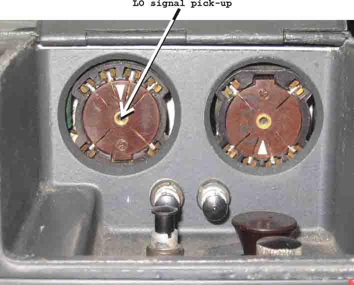
Figure 2. The sockets of RV12P2000 are clearly visible (left the LO and on the right the mixer valve).
The RV12P2000 valve (tube) is most suitable for us. We can see that the oscillator valve base (on the left) is fit with an easily accessible 3 mm threat. Originally meant for locking a valve-puller.
I regard the availability of a copy of the Köln E52 manual (or schematic diagram). *It is possible to copy an E52a schematic diagram at the "E52 prototype V1" page, please consider the instruction to reproduce it in good quality.
First:
We set the main calibration trimmer in its central position.
Now we switch on the BFO (Schwebungsüberlagerer A1), and tune the receiver zero-beat (Schwebungslücke) at a particular frequency (favourable is somewhere at the higher end of range Band III, though, not at its far end) (8-9 MHz will do, but it is not critical).
We then lock a tiny 3 x 3 mm bolt in the base of the left (LO) RV12P2000.
Then, we solder a small capacitor of about 2,2 pF to the bolt-head.
Next, we have to link its open end, by means of a coaxial cable (ground to the chassis should be stable), to an electronic counter, which should measure down to 1 Hz. When the LO level, particularly at band IV or V is not appropriate, I insert a very simple transistor amplifier (made in flying-wire technique and fed by means of a 9 volts battery, don’t forget to switch it off!).
We will discover, that the oscillator frequency has changed a tiny bit. By slightly re-adjusting the main calibration trimmer, we tune the receiver again at zero-beat. The insertion of a small capacitance of say 2,2 pF, guarantees us that only very minor loading(pulling) of the oscillator stage can occur.
Important is, that some have suggested that a signal pick-up can be accomplished by means of a probe through one of the holes in the oscillator stage cover plate. This is, in my vision, totally inadequate, as it disturbs the electrical field (lines) inside the coil section too much!
|
|
Frequency L |
Frequency H |
off-set L Δ f |
off-set H Δ f |
|
Receiver freq. |
17600 kHz |
25100 kHz |
|
|
|
= LO closed |
18608,06 kHz |
26111,06 kHz |
|
|
|
= LO open |
18594,25 kHz |
26119,50 kHz |
-13,81 kHz |
-8,44 kHz |
|
Tune LO at |
|
|
18586,19 kHz |
26091,56 kHz |
|
Receiver freq. |
9950 kHz |
17700 kHz |
|
|
|
= LO closed |
10950,43 kHz |
18696,28 kHz |
|
|
|
= LO open |
10924,0 kHz |
18689,88 kHz |
-26,43 kHz |
-6,4 kHz |
|
Tune LO at |
|
|
10923,57 kHz |
18693,6 kHz |
|
Receiver freq. |
5980 kHz |
10050 kHz |
|
|
|
= LO closed |
6968,00 kHz |
10939,99 kHz |
|
|
|
= LO open |
6914,06 kHz |
10897,50 kHz |
-53,94 kHz |
-42,49 kHz |
|
Tune LO at |
|
|
6926,06 kHz |
11007,51 kHz |
|
Receiver freq. |
2980 kHz |
6040 kHz |
|
|
|
= LO closed |
3977,90 kHz |
6986,27 kHz |
|
|
|
= LO open |
3974,52 kHz |
6993,20 kHz |
-3,38 kHz |
+6,93 kHz |
|
Tune LO at |
|
|
3976,62 kHz |
7046,93 kHz |
|
Receiver freq. |
1480 kHz |
3020 kHz |
|
|
|
= LO closed |
2467,57 kHz |
3972,36 kHz |
|
|
|
= LO open |
2460,2 kHz |
3968,60 kHz |
-7,37 kHz |
-3,76 kHz |
|
Tune LO at |
|
|
2472,63 kHz |
4016,24 kHz |
LO = Local oscillator; closed means cover being mounted; open means screening-off cover being removed (taken off); L = L-end and C = C-end of a band. Table made for Köln E52a1, scale number 1876, measured on 1 May 1992
Figure 3. An example how one can approach this calibration task.
Please bear in mind, that such an alignment has to be repeated time and agin. Sometimes, at each frequency range ten or even more times. One will discover, however, that after every L-end + C-end adjustment, the off-set from its nominal value(Tune LO at) is reducing(decreasing). We have to start our alignment, always, at the L-end of the band first!
You can finally check your alignment, by closing the metal screening cover and notice all calibration points with an off-set of + 1000 kHz. Thus, for instance, projected 17600 kHz read 18600 kHz (17600 + 1000 kHz of IF). Though, before finishing this project, tune first (again) zero beat at a particular frequency like the one you have received before you started this calibration procedure (all modules must be in place, of course). Remove the 3 mm bolt and tune, by means of the central trimmer, at zero beat again.
Final comments
It has been proved since, that this calibration procedure guarantees a long term accuracy of microfilm scale reading. I started this kind of calibration procedure somewhere in the 1980s.
This re-calibration procedure can be fully commenced, without front modules being in place (like IF/ZF, demodulator/BFO and/or low frequency module). There cannot occur any interpretation error, as the only thing that matters is the counter-display!
I have restored,
all together approximately 40 Kölns (however, not all with this advanced
procedure).
Some Kölns showed very unusual de-focussing of the projected read-out (read-out of the frosted glass window). This phenomenon could be solved (anticipated) by means of a paper-ring, placed between the main mounting and the microfilm glass disc. There may well be another or even better solution to it. But this procedure is simple, adequate and does not endanger the projecting system, irreversibly, at all.
Telefunken may have used a comparable (off-set) procedure, be it, that electronic high frequency counters had not yet been invented. What they might have done is: they used wavemeters instead. This was a very popular technique and was comparable to the very famous BC221, of US origine. Alternatively, one also could make use of a very accurately calibrated receiver. This could cause, however, ambiguities. They, nevertheless, must have considered frequency shift, when a cover-plate (Abschirmhaube) of the oscillator stage (LO) had been taken-off, especially during the pre-calibration procedure! For practical reasons, they might have considered (used) standard tables, giving (providing) off-set and other kinds of information.
For us
significant is, that after the Köln receiver had left Telefunken’s alignment
field, individual microfilm scale calibration had been carried out! And small
deviations were being compensated (more or less nilled) after the calibration
procedure. A not optimally match to LO frequency curve was only causing
deviation of receiver sensitivity.
But, we can not make use of this equalising phenomenon. Because, the frequency
response of the Köln microfilm scale is a given(elementary) factor. We are thus
forced to restore the original “φ versus Δf” response.
Finally
The black scales with white figures, had all been calibrated individually.
Telefunken employed, in these cases, their so-called “Eichmaschine” (automatic
photographical scale calibration apparatus). All Telefunken microfilm scales, had been
calibrated this way. (Such as: Köln, Ulm, Main,
Wupper, AS60/M1K, ...)
Telefunken received for this “automatic scale calibration apparatus” patent number
DE691884, the inventors were Protze and Weber. The application date was 20 July
1938 and it was granted on 6 May 1940. Regard my “German patent selection”;
enter, for instance, the keyword: Eichmaschine
[4].
For your convenience:
Calibration table to Köln E52
(select this table, and copy (link) it to your "clip board" (Ctr+C), and paste it in Word or WordPerfect (Ctr+V)
|
|
Frequency L |
Frequency H |
off-set L Δ f |
off-set H Δ f |
|
Receiver freq. |
17600 kHz |
25100 kHz |
|
|
|
= LO closed |
kHz |
kHz |
|
|
|
= LO open |
kHz |
kHz |
kHz |
kHz |
|
Tune LO at |
|
|
kHz |
kHz |
|
Receiver freq. |
9950 kHz |
17700 kHz |
|
|
|
= LO closed |
kHz |
kHz |
|
|
|
= LO open |
kHz |
kHz |
kHz |
kHz |
|
Tune LO at |
|
|
kHz |
kHz |
|
Receiver freq. |
5980 kHz |
10050 kHz |
|
|
|
= LO closed |
kHz |
kHz |
|
|
|
= LO open |
kHz |
kHz |
kHz |
kHz |
|
Tune LO at |
|
|
kHz |
kHz |
|
Receiver freq. |
2980 kHz |
6040 kHz |
|
|
|
= LO closed |
kHz |
kHz |
|
|
|
= LO open |
kHz |
kHz |
kHz |
kHz |
|
Tune LO at |
|
|
kHz |
kHz |
|
Receiver freq. |
1480 kHz |
3020 kHz |
|
|
|
= LO closed |
kHz |
kHz |
|
|
|
= LO open |
kHz |
kHz |
kHz |
kHz |
|
Tune LO at |
|
|
kHz |
kHz |
LO = Local oscillator; closed means cover being mounted; open means cover being removed (taken off) L = L-end and C = C-end of a band.
Literature and
references
1
www.xs4all.nl/~aobauer/nieuwe_pagina_1.htm When on line:
nieuwe_pagina_1
2 www.xs4all.nl/~aobauer/luft-bodenprogr.htm When on line: luft-bodenprogr
3 Wie Hoch war
die Köln Stückzahl? (our archive reference Z 1074, Z 962/11)
4.
www.xs4all.nl/~aobauer/german_patents.htm
When on line: german_patents
Back to: Köln E52 main page
Back to: Handbooks papers and product information
![]()