Kurzwellen-Sender 1,4 kW,
AS 60
Ln 21210
mit Netzanschlußgerät Ln 21211
Swiss
nomenclature: M1K
This magnificent transmitter was designed in 1942/43 and produced by Telefunken.
However, the Germans themselves purchased only a few sets. (these units might have
been only employed by Goering's staff-communication group)
The Swiss Army purchased these transmitters about 1944/45. Assemblage took place by the Swiss Autophon company.
The entire wireless station SE-403 cost was: inclusive the truck, Swiss receiver type E 41 and mobile generator: 145500 SF (price 1946-1950).
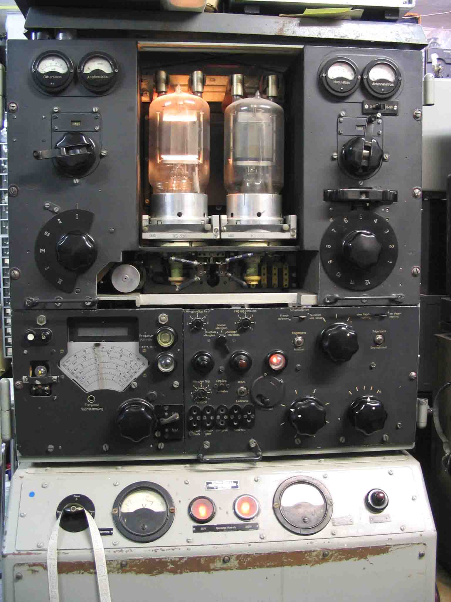
Front panel, with door being opened.
The filament of the big transmitter valve RS384, on the right-hand side, has been disconnected, to limit the antenna power to maximally 700 watts.
The driver and modulator cabinet has been pulled out of the main-frame. Disconnecting the mechanical link between the band-switch and frequency tuning.
The valve (tube) on the left-hand side is Rö 1 the power oscillator valve. This transmitter could be tuned between 3 and 25 MHz. Max. antenna power 1400 watts.
Very remarkable was, that according the specifications the frequency stability was better than 5 ppm/K. If we consider that they employed power valves (anode dissipation of 50 watts), then very special circuitry had to be maintained. Let us consider the oscillator circuit shown below.
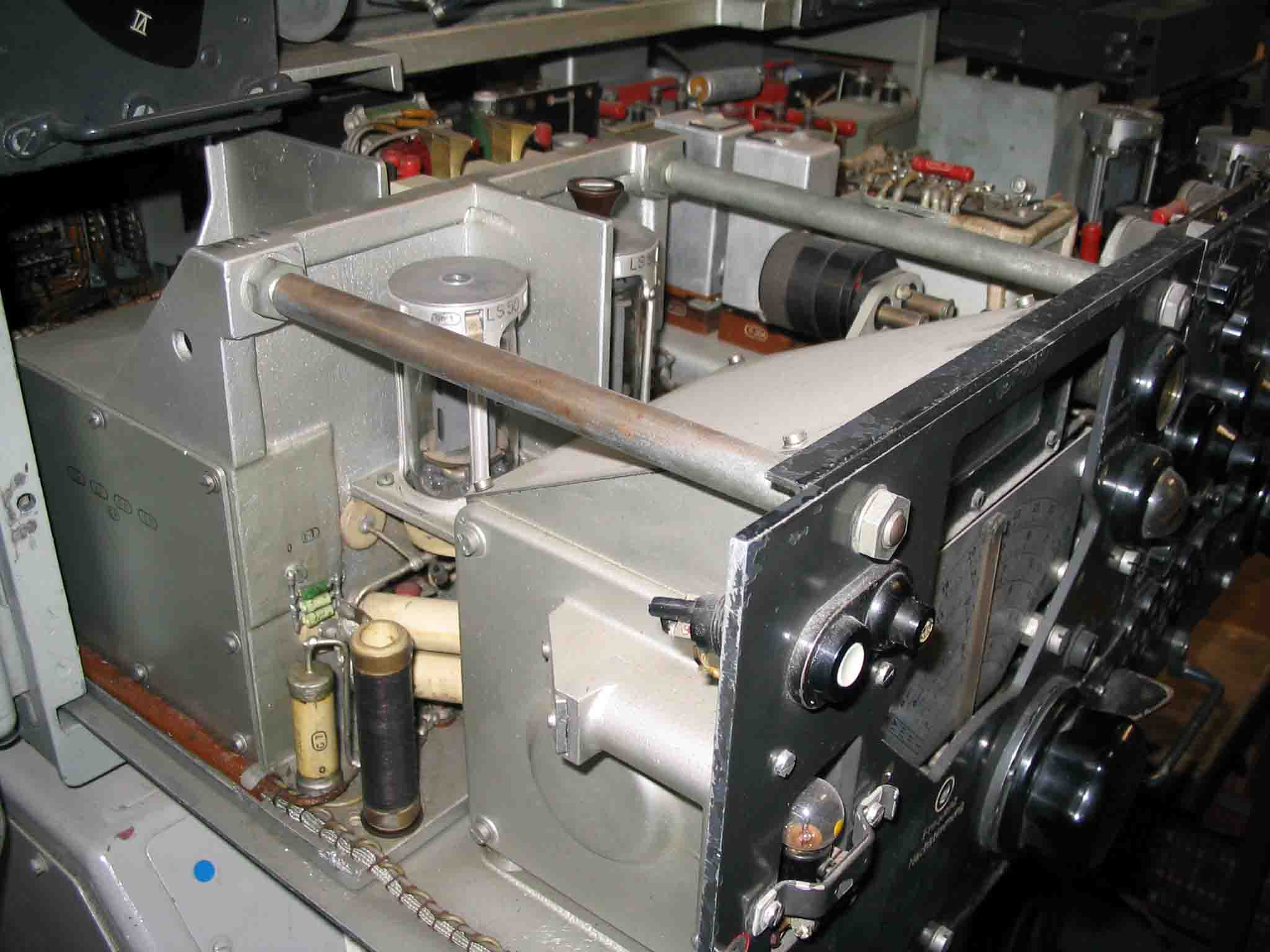
They achieved a remarkable increase in frequency stability, by lowering the influence of the anode versus the oscillator coil. Consequently, increasing the effective Q of it. As we know, that the transmission was blocked (keyed) by means of grid-blocking of the oscillator stage, then we understand that the LS50 oscillator valve changed it dissipation constantly. When we consider that the temperature of a valve anode is changing, then we may expect that its capacitance Cak has to change as well. Consequently, changing the signal frequency. However, when the Cak is parallel to the configuration of C 11 (200 pF) and in series with C 10 (100 pF) then we may regard that the nominal influence of Δ Cak is being reduced. For this occasion we have neglected the Miller-effect. Most capacitors in this circuit are hermetically sealed-off from their environment. Inside it contained two cylindrical (coaxial) capacitors of different Tc, as to minimize the overall frequency / temperature response. These kinds of special capacitors were manufactured by Hescho and were supplied with tolerances of 0.5 %, and are visible in the picture above. See the two horizontally mounted porcelain tubes just behind the vertically mounted wire-wound RF choke.(left-hand side)
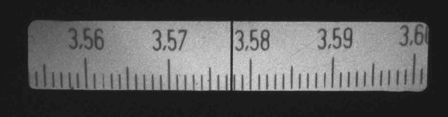
The frequency fine reading is projected on a frosted glass window.
The scale space between 3570 and 3580 kHz is 16 mm. This kind of frequency reading (dial) was very exceptionally in the 1940s.
The transmitter is tuned at 3577.7 kHz, which calibration today still is within its specs (after > 62 years)!
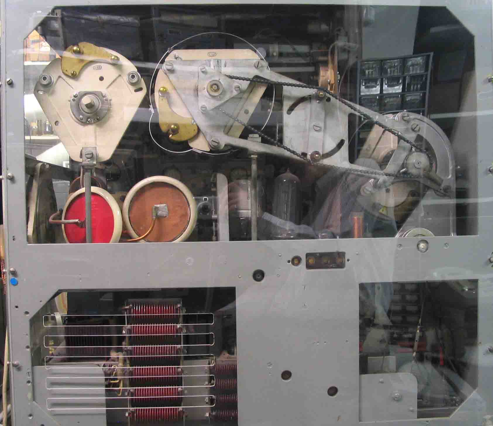
A view of the
backside of the transmitter.
The metal cover plate being removed, and is replaced by a perspex safety window
A chain
links the PA coil with its driver tuning.
On the right-hand side between the lower and upper cabinet, we see the cable
link of the band switches. On the left-hand side in the upper cabinet, we see
the antenna tuner. The high voltage disk capacitors (15 kV working voltage) were
part of the antenna tuner.
Back to: Archive displays
Back to: Exhibits
![]()